Profile Projector: Complete Guide to Optical Comparators for Industrial Metrology
By Radical Scientific — Applications TeamPublished: 12 June 2026
Focus: A complete technical and application guide to profile projectors — covering the underlying optical principle, the difference between vertical and horizontal optical comparators, a comparison with alternative measurement technologies, key specifications, and a step-by-step selection framework to help you choose the right profile projector for your manufacturing or quality control application.
The profile projector is one of the most reliable and cost-effective tools in industrial dimensional metrology. It has been in continuous production use since the 1940s, and remains the first-choice instrument for fast, non-contact contour inspection of precision components in industries ranging from automotive tooling to medical device manufacturing. If your quality lab needs to inspect complex profiles, threads, gears, stamped parts, or small turned components at high throughput, a profile projector delivers results that no other technology matches at the same price point.
What is a profile projector?
A profile projector — also known as an optical comparator — is a precision metrology instrument that projects an enlarged, high-contrast silhouette of a workpiece onto a large viewing screen. The operator measures the projected image directly on the screen using graduated overlays, digital readout (DRO) systems, or geometric data processors, allowing accurate dimensional measurement without physical contact with the part.
The core principle is straightforward: a telecentric optical system illuminates the workpiece from below (contour illumination) or above (surface illumination), and the resulting magnified image is projected onto a frosted glass screen — typically 300 mm to 600 mm in diameter. The screen can be rotated 360° with vernier resolution for angular measurement. The work stage moves on precision X-Y linear slides with digital readout to 0.001 mm resolution, enabling fast and repeatable measurement of lengths, radii, angles, and complex contour profiles.
The terms profile projector, optical profile projector, and optical comparator all refer to the same instrument. "Optical comparator" is the more common term in North America; "profile projector" and "optical profile projector" are preferred in Europe, Japan, India, and most of Asia. All three names describe the same instrument performing the same measurement function.
How does a profile projector work?
A profile projector operates on three coordinated optical and mechanical systems:
Telecentric optical system
The key optical requirement of a profile projector is telecentricity — the exit pupil of the projection lens must be at infinity. In a telecentric system, all principal rays are parallel to the optical axis, which means the magnification of the projected image remains constant regardless of the height position of the workpiece on the stage. Without telecentricity, a part placed slightly above or below the focal plane would appear magnified differently and measurement would be inaccurate. All high-quality profile projectors use telecentric zoom or fixed lens systems to guarantee constant magnification across the full depth of the workpiece.
Illumination system
Two distinct illumination modes are used depending on what is being measured:
Contour (transmitted) illumination: Light is projected upward through the transparent work stage from a high-brightness halogen or LED source positioned below. The workpiece blocks the light, creating a sharp, high-contrast silhouette on the screen. This is the standard mode for profile and contour measurement of opaque components.
Surface (reflected) illumination: Light is directed obliquely onto the top surface of the workpiece from above. The reflected light is projected onto the screen, allowing inspection of surface features, markings, defects, and non-transparent workpieces such as plastic mouldings, printed circuit boards, and paper or textile samples.
Precision X-Y measuring stage
The work stage moves on hardened precision linear slides in two axes (X and Y). A digital readout (DRO) system — incorporating optical linear encoders or precision glass scales — measures stage displacement to 0.001 mm (1 µm) resolution. The operator positions the stage so the edge or feature of interest aligns with a reference line on the screen, then reads the dimensional value directly from the DRO display. Incremental and absolute measurement modes, zero-setting at any position, and direct tolerance comparison (go/no-go display) are standard DRO functions.
Types of profile projectors — vertical vs horizontal
Profile projectors are divided into two fundamental configurations based on the direction of the optical beam. Choosing between vertical and horizontal is the most important single decision when specifying a profile projector, and it is driven entirely by the geometry of the workpieces you need to inspect.
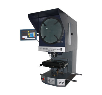
Vertical profile projectors
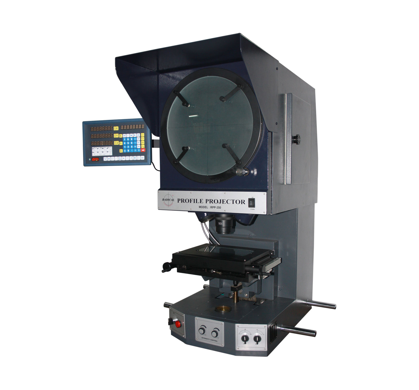
In a vertical profile projector, the optical beam travels vertically — upward from the illumination source through the work stage and into the projection lens above. The workpiece is placed flat on a horizontal glass stage. This is the most common configuration and is suitable for the majority of precision components: flat stampings, moulded plastic parts, punched sheet metal, PCBs, drilled or milled profiles, small gears, washers, and any component that can be laid flat on the stage.
Vertical projectors are available in two form factors:
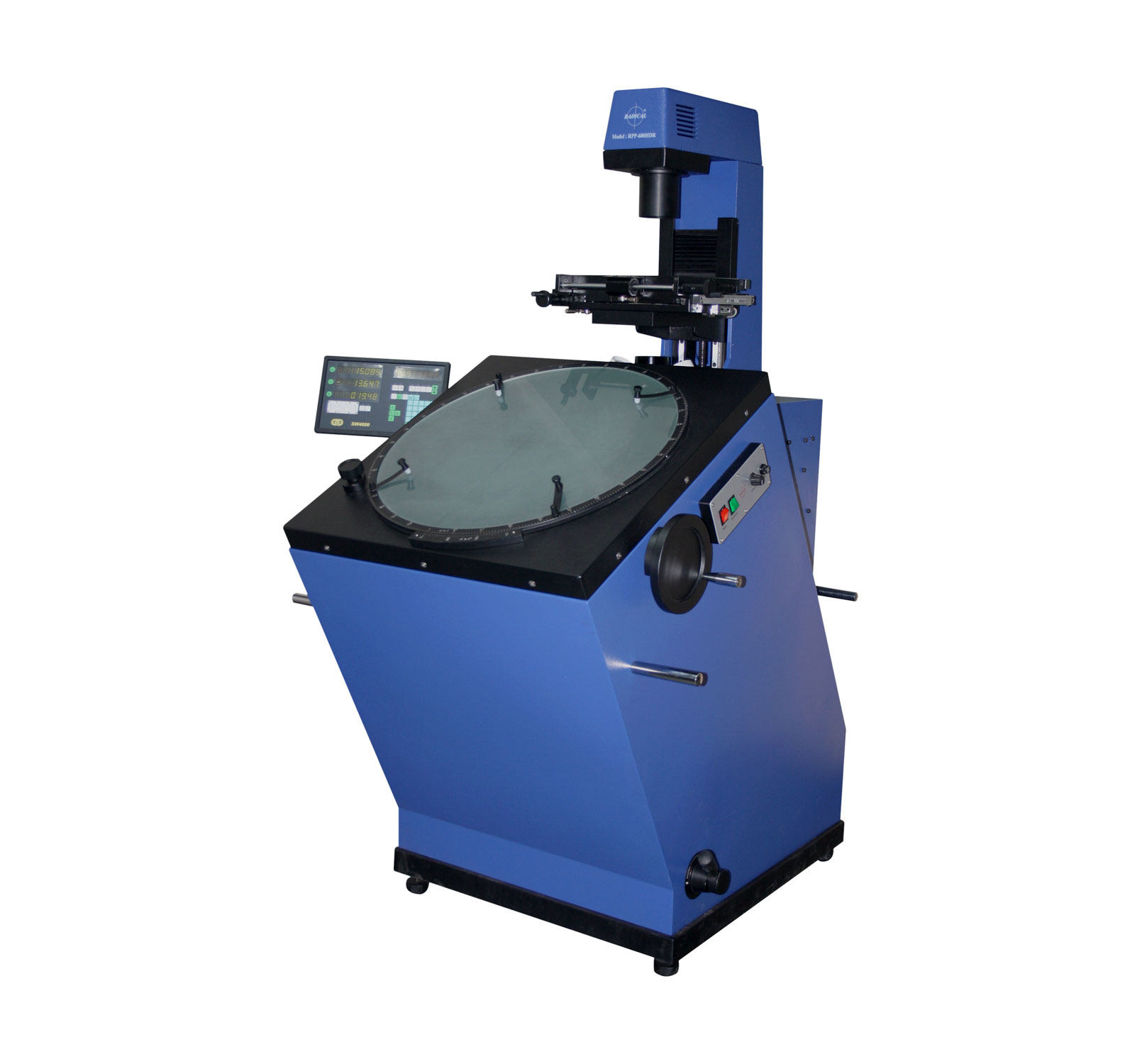
Floor-standing (column) type: The optical column, projection screen, and work stage are mounted on a floor pedestal. Screen sizes of 500 mm and 600 mm are typical. The larger stage travel and heavier load capacity make floor-type projectors the standard for production-floor quality control in automotive, aerospace, and heavy engineering environments.
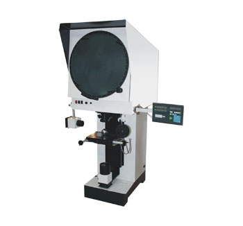
Benchtop (tabletop) type: A compact version mounted directly on a workbench. Screen sizes of 150 mm to 400 mm. Benchtop projectors occupy minimal floor space and are well suited to workshop inspection cells, laboratory quality benches, and applications where smaller component sizes allow a smaller screen diameter.
Floor-standing: RPP-500V — 500 mm screen, heavy-duty production floor modelBenchtop: RPP-350 — 350 mm screen, compact workshop and lab model
Horizontal profile projectors
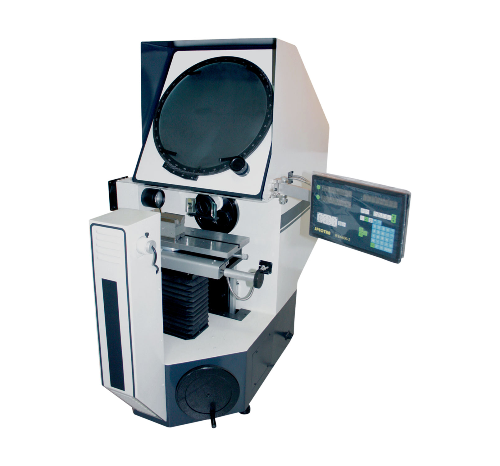
In a horizontal profile projector, the optical beam travels horizontally — from the illumination source through the workpiece to the projection lens and screen at the far end of the instrument. The workpiece is held vertically in V-blocks, between centres, or in a chuck on the work stage. This geometry is specifically optimised for long cylindrical, shaft-type, or rotationally symmetric components that would be difficult or impossible to inspect on a horizontal stage without complex fixturing.
Primary applications of horizontal profile projectors include: precision screw threads (form and pitch measurement), hob and gear tooth inspection, cutter profiles, lathe tool geometry, cylindrical workpieces, and turned components with complex longitudinal profiles. If your quality lab inspects turned parts, threads, or hobs as a primary workload, a horizontal projector is the correct choice.
Vertical profile projector (RPP-60) — workpiece laid flat on horizontal stageHorizontal profile projector (RPH-400) — workpiece held vertically between centres
Selection Rule: Choose a vertical profile projector for flat, moulded, or irregular components that rest naturally on a horizontal stage. Choose a horizontal profile projector for long, cylindrical, threaded, or shaft-type workpieces. If your lab handles both workpiece types in significant volume, consider one of each — or a horizontal projector with vertical adapter fixturing.
Profile projector vs CMM vs vision system — which is right for your lab?
The profile projector is one of several non-contact dimensional measurement technologies available to quality engineers. Understanding where it sits relative to Coordinate Measuring Machines (CMMs), vision measuring systems, and bench micrometers will help you justify the investment and specify the right tool for each measurement task.
Feature
Profile Projector
CMM
Vision System
Bench Micrometer
Measurement type
2D contour, length, angle, radius
3D coordinates, form, position
2D dimensions, surface features
Linear diameter, thickness
Contact with part
Non-contact
Contact probe (usually)
Non-contact
Contact
Measurement speed
Very fast (seconds)
Slow to moderate
Fast (automated)
Moderate
Operator skill required
Low to moderate
High (CMM programming)
Moderate
Low
Cost
Low to moderate
High
Moderate to high
Very low
Contour profile inspection
Excellent
Good (with scanning probe)
Good
Not applicable
Template overlay comparison
Yes — direct visual
Software only
Software only
No
Thread and gear inspection
Excellent
Good
Limited
Thread gauge only
Typical resolution
0.001 mm
0.0001 mm
0.001–0.005 mm
0.001 mm
Best for
High-volume production inspection
Complex 3D parts, tight tolerances
Multi-feature automated inspection
Simple go/no-go gauging
Key Insight: The profile projector dominates in high-throughput production environments because a skilled operator can inspect components against overlay templates with zero programming required — far faster than a CMM for the same 2D inspection task. A CMM offers superior accuracy and 3D capability but at a significantly higher cost and lower throughput for routine production-floor inspection. For most stamping, turning, moulding, and toolmaking quality workflows, a profile projector delivers an excellent balance of speed, accuracy, and cost.
Profile projector applications — industries and use cases
The profile projector is a universal tool across precision manufacturing. Below are the primary industries and specific inspection tasks where optical comparators are used daily.
Automotive manufacturing and tooling
Automotive component manufacturers use profile projectors for stamped metal part inspection (body panels, brackets, clips), gear tooth profile verification, thread gauging on fasteners, die and punch profile inspection, and quality audits on turned transmission and engine components. Profile projectors are common on production lines in both OEM and Tier 1 supplier quality labs across India's automotive manufacturing clusters.
Aerospace and precision engineering
Aerospace quality standards demand traceable dimensional measurement at micrometre resolution. Profile projectors are used for turbine blade root profile inspection, precision gear tooth verification, nozzle and orifice geometry measurement, thread form inspection on critical fasteners, and contour verification of complex machined brackets and housings. Floor-standing vertical projectors with 500–600 mm screens and calibrated magnification accuracy are the standard in aerospace quality labs.
Tool and die making
Profile projectors are an essential tool for the die maker's bench. The ability to project a die profile directly against a design overlay chart — and visually confirm conformance to nominal geometry without any calculation — makes the optical comparator uniquely valuable at the tool-making stage. Punch profiles, die radii, relief angles, and complex form tools can all be verified in seconds against scaled overlays at the bench.
Gear and thread inspection
Thread form measurement — verifying flank angle, pitch, root radius, and crest geometry — is one of the oldest and most reliable applications of the horizontal profile projector. Metric, UNC, UNF, BSW, and proprietary thread forms can all be measured by comparing the projected image against standard thread overlay charts at the appropriate magnification. Similarly, gear tooth form, involute profile, and pressure angle can be verified on a profile projector faster than on a gear measuring centre for routine batch inspection.
Medical device and surgical instrument manufacturing
The medical device industry requires precise dimensional verification of surgical instruments, implant components, needles, cannulae, and micro-precision parts. Profile projectors — particularly benchtop models with small screen sizes and high magnification — are used for verifying needle tip geometry, cannula bevel angles, implant surface profiles, and the dimensions of miniature stamped and turned components. Non-contact measurement preserves part cleanliness and avoids measurement-induced damage on delicate surfaces.
Electronics and PCB inspection
Surface illumination mode on a profile projector allows inspection of PCB solder joint profiles, connector pin geometry, lead pitch and coplanarity, and fine component placement. Digital profile projectors with camera output can capture component images for quality records and SPC analysis.
Key specifications to evaluate when choosing a profile projector
Specifying a profile projector correctly requires understanding how each parameter relates to the components you need to measure. Below is a systematic guide to the key specifications.
Screen diameter
The projection screen diameter is the most visible specification and directly determines the largest workpiece cross-section that can be measured in a single view. Common sizes are 300 mm, 400 mm, 500 mm, and 600 mm. A 300 mm screen is adequate for components up to approximately 25–30 mm cross-section at 10× magnification. A 600 mm screen at 10× covers a workpiece of approximately 55–60 mm. Choose the screen size based on your largest typical component, not your smallest — you can always measure a small part on a large screen, but cannot measure a large part on a small screen.
Magnification range
Standard magnification is 10× on most models. Optional lens sets provide 20×, 25×, 50×, and 100× for finer detail inspection at the cost of reduced field of view. For most production inspection (stampings, turned parts, gears), 10× and 20× cover the majority of work. Thread and gear tooth inspection typically uses 25× to 50×. Fine surface feature inspection and miniature medical components may require 50× to 100×. A turret-mount lens system allowing fast magnification switching without stage repositioning is important for labs inspecting multiple component types.
Stage travel (X-Y axis)
Stage travel determines the maximum linear measurement range in each axis. Typical values are 200×150 mm (benchtop) to 300×250 mm (floor models). For components larger than the stage travel, the part must be repositioned — acceptable for reference measurements but awkward for continuous contour tracing. Ensure your largest component fits within the stage travel of the selected model.
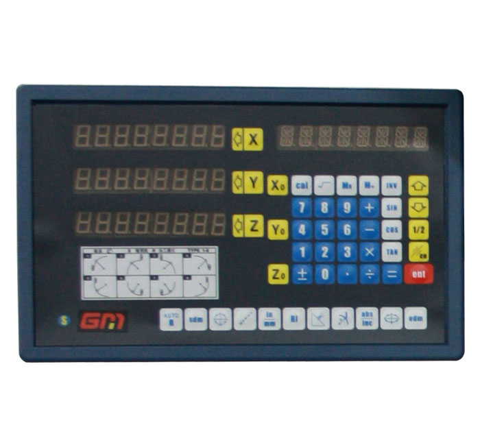
Digital readout (DRO) resolution and type
Modern profile projectors use optical linear encoders (glass scales) with 0.001 mm (1 µm) readout resolution as standard. The DRO display should provide: absolute and incremental modes, edge detection (zero at any edge), direct tolerance comparison with go/no-go output, and data output to PC or printer. Higher-specification systems add geometric data processors that calculate diameter, radius, angle, and runout from a sequence of point measurements — significantly accelerating complex inspection routines.
Profile projector DRO display — 0.001 mm resolution with incremental, absolute, and go/no-go tolerance modes
Illumination system
Standard illumination uses a 24V, 150W halogen lamp with forced-air cooling and variable intensity control. This provides high brightness for clear contour images even on polished or reflective surfaces. LED illumination is available on newer models and offers longer life and consistent colour temperature, but verify that the LED system provides adequate screen brightness at your required magnification before specifying. Green filter selection (standard) improves edge definition for contour measurement; yellow filter is optional for some surface materials.
Telecentric optics and magnification accuracy
Magnification accuracy should be specified as a percentage. Quality profile projectors achieve ±0.05% on contour illumination and ±0.1% on surface illumination. At 10× magnification on a 500 mm screen, ±0.05% corresponds to a maximum measurement error of ±0.25 mm across the full screen — acceptable for most production inspection. For tighter tolerance work, confirm that the telecentric optics of the selected model are properly centred and that the manufacturer provides in-house calibration certificates traceable to national standards.
Specification Tip: Do not over-specify. A well-maintained 10× profile projector with a 400 mm screen, 0.001 mm DRO, and calibrated optics handles 90% of production inspection requirements. Invest the remaining budget in accessories (overlay charts, V-blocks, edge detectors, DRO with geometric processor) that directly reduce inspection time rather than in a larger screen size you will rarely need.
Profile projector selection checklist
Use this checklist to define your requirements before requesting a quotation. Answering each question precisely will ensure you receive a profile projector correctly configured for your application and budget.
1
Define Workpiece Geometry
Flat components → vertical projector. Long cylindrical or threaded components → horizontal projector. Mixed workload → consider both configurations or a horizontal projector with vertical fixturing.
2
Select Screen Size
Measure your largest typical component cross-section. At 10× magnification, the workpiece must fit within the screen diameter. Add 20% margin for positioning flexibility.
3
Confirm Stage Travel
Verify that the X-Y stage travel covers the maximum measurement length you require in each axis. For long components, confirm the workpiece repositioning tolerance is acceptable for your measurement plan.
4
Specify Magnification Set
List the magnifications you require. Most labs need 10× and one additional lens (20× or 50×). Confirm the lens turret accepts multiple lenses for fast changeover.
5
Choose DRO / Data System
Basic DRO for simple length measurement. Geometric data processor if you need automatic calculation of diameters, radii, angles, and runout. PC output for SPC data collection.
6
Identify Required Accessories
Overlay charts (thread, gear, angle), V-blocks (for cylindrical parts), edge detector probes, swivel centre supports, and calibration glass scales should be ordered with the instrument for immediate use.
Quality Labs and NABL Accreditation: If your quality lab is NABL-accredited or ISO/TS 16949 certified, confirm with your profile projector supplier that a calibration certificate traceable to NABL/NPL national standards is available at the time of delivery. Ask for this specifically during the quotation stage.
Profile projectors from Radical Scientific
Radical Scientific Equipments Pvt. Ltd. is an India-based manufacturer of precision metrology instruments including profile projectors and optical comparators. Our profile projector range covers vertical and horizontal configurations — from compact benchtop models for workshop quality cells to large-format floor-standing optical comparators for aerospace and heavy engineering production lines.
To find the right model for your application, discuss your workpiece geometry, required screen size, and inspection volume with our team and we will recommend the correct configuration.
Explore the full Radical Scientific profile projector range:
What is the difference between a profile projector and an optical comparator?
A profile projector and an optical comparator are identical instruments — both project an enlarged silhouette of a workpiece onto a screen for dimensional measurement and contour inspection. The term "optical comparator" is the dominant name in North America and the UK, while "profile projector" is the preferred term across India, Europe, and East Asia. Both names appear in ISO and ASTM standards, and both refer to the same measurement principle and instrument design.
How accurate is a profile projector?
A well-maintained profile projector with calibrated telecentric optics achieves linear measurement accuracy of ±0.001 mm to ±0.005 mm depending on the screen size, magnification, and DRO system. Magnification accuracy is typically specified at ±0.05% for contour illumination — at 10× on a 400 mm screen, this corresponds to an image magnification error of ±0.2 mm across the full screen diameter. For most production inspection tolerances (±0.01 mm to ±0.1 mm), this accuracy is more than adequate.
What is an overlay chart (template chart) on a profile projector?
An overlay chart — also called a template chart or projection chart — is a scaled drawing of the nominal component profile, printed on transparent material, that is attached to the profile projector screen. The operator places the component on the stage and projects its magnified image onto the screen. The projected image is then visually compared against the overlay chart. Any deviation from the nominal profile is immediately visible as a gap or overlap between the image and the chart boundary. Overlay charts are produced at the projector's magnification (e.g., a component at 10× magnification requires a 10:1 scale overlay chart). They are the fastest possible go/no-go inspection method for complex contour profiles.
When should I choose a floor-standing profile projector over a benchtop model?
Choose a floor-standing profile projector when: your workpieces are larger than approximately 50 mm in cross-section; your production volume requires a larger stage travel (300×200 mm or greater); you need a 500 mm or 600 mm screen for full-component visibility; or your environment requires a heavy-duty instrument that can withstand continuous production-floor use. Choose a benchtop profile projector for smaller components, laboratory or workshop environments with limited space, and applications where portability or a lower capital investment is a priority.
Can a profile projector replace a CMM for production inspection?
For 2D profile inspection tasks — contour measurement, thread form verification, gear tooth profiles, angular and linear dimensions — a profile projector is significantly faster and more practical than a CMM for routine batch inspection. A CMM is the superior choice when you require true 3D measurement, tight tolerance positional verification (GD&T), or automated multi-point inspection of complex 3D surfaces. Many quality labs use both instruments: a profile projector for high-throughput 2D production inspection and a CMM for first-article inspection, complex 3D parts, and PPAP documentation.
What is the price of a profile projector in India?
Profile projector pricing in India varies significantly based on screen size (300 mm to 600 mm), configuration (benchtop vs floor-standing vs horizontal), DRO specification, magnification set, and included accessories. Benchtop models are generally the most affordable entry point; large-format floor-standing and horizontal projectors with full DRO and data output are at the higher end of the range. The best approach is to define your screen size, workpiece type, and required magnification first — then request a configuration-specific quotation from the manufacturer: Request a Quote from Radical Scientific.